The Orbe POV v1.0
This is the page describing first prototype of The Orbe: a fully 3D printed persistence of vision display.
Motivation
There were two main motivations for this 3-weeks-long project:
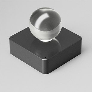
- A few weeks ago we found a small, 9 mm in diameter, glass sphere. Wouldn't be could to include a POV system inside of it?
- There is a 3D printed contest!
Here are the results of 3 weeks of hard work. I'll try to cover it as much as possible, including pictures and videos. It will go from the CAD design to the assembly and programming.
If you have any comments, you can reach me @mdblabs. Enjoy!
3D Design*
Main idea was simple: just make a rotating sphere, holding from a brushless motor, on a base. Main problem on POV systems is how to provide the rotating part power. Normally, two solutions are implemented: battery powered or power transmission to the rotating part by any means.
While I didn't want to use any battery (just keep the gadget connected to the AC mains), I thought about power transmission on brushed motors. I will use a brushless motor to move the sphere, and a brush contact to power it. Nice!
Having a squared based, holding all the electronics and the PSU plus the sphere was the plan. Everything should be inside an enclosure. Also, as we had a 9 cm in diameter crystal sphere, electronics shoud be fit inside of it.
I made a few sketches and renders. They looked nice, so, I kept myself working on those ideas.
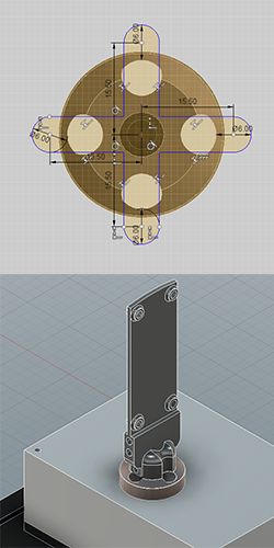
Then, I modeled the base, the brushless motor and the PSU. Motor was a small one: the 2204 1400 KV model from RC Timer with its 10 A ESC.
To hold the electronics, a support was designed to fit the Arduino/Genuino MKR1000. A second problem on the POVs is how to send not only power, but data to the rotating part. MKR1000 was an-easy to use, full-solution, which includes enough pins, plus a built-in wireless modem.
A pair of arms were designed to hold the LEDs: one for the red ones, and a the other one for the greens. Original idea was to use 3 colors, but that would make the desing very complex. Also, using just two arms will keep the rotating part balanced. Also, a cylindrical column was included. This column will keep the arms straight during rotation, and will hold a pair of slots. On those slots a 5 mm copper film will be glued, to transmit power to the sphere. On each arm, a pair of spring based carbon brushes will make contact with the copper. An external, screwed ring, will hold everything tight
Two more small arms were designed to carry a IR sensor, to measure half rotation. Also, on the base, a column with a thin plate will act as optical interrupt.
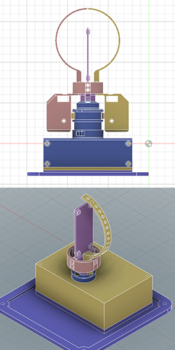
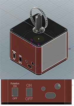
Finally, a control panel and top and lateral panels were included. It has a AC connector, two LEDs (power ON and rotation indicator) and two switches: Power ON/OFF and Rotation ON/OFF.
* CAD design was done using Autodesk Fusion 360.
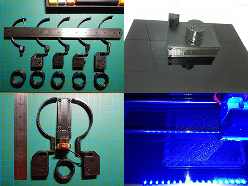
3D Printing*
Several prototypes were printed, in order to adjust final design, like sphere or sensor arms. Also, to adjust tolerances for screw holes and assembly joins.
Little sanding was only necessary on optical switch column, to let the IR sensor pass trought (see Electronics and Lesson Learned), although tolerances for werent good enought and was deprecated.
List of printed parts is:
| Part Name | STL | Needed |
|---|---|---|
| Base | base.stl | x1 |
| Arduino and Electronic support | electronic_support.stl | x1 |
| LEDs rm | led_arm.stl | x2 |
| Motor support | main_support.stl | x1 |
| Control panel and enclosure | panel.stl | x1 |
| Conection ring | ring.stl | x1 |
| Sensor arm | sensor_arm.stl | x2 |
| Side panels | side.stl | x3 |
| Top panels | top.stl | x2 |
Everything was assemblied using M3 and M4 screws, and nylon nuts (see Assembly). Every piece was printed on black or orange PLA at 210 ºC and 70 mm/s speed.